Multi-Level Switch Small Size from Almeg Controls

Multi Level Switch, Small Size
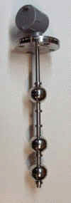
Small Size multi level controls are similar to the larger level control model in so much as doing the same job - only this model uses smaller floats and probe allowing for tight or constricted 

applications. Choose from one to four stations in most material and configurations.


Click here Part Numbers in pdf.      


Operating Range


Material

Pressure

Temperature

Specific

Gravity

 
316 Stainless Steel 750 psi -040 to 300 deg F 0.75 Other Sp.Gr Available
PVC 100 psi - 10 to 140 deg. F 0.6  
Kynar 100 psi -10 to 240 F 0.6  
Polypropylene 100 psi 100 deg. F 0.7  
Buna Material 200 -40 to 225 F OIl 0.55 Other Sp.Gr Available

Stainless Steel Probe Assembly Part Numbers 

Stainless

Fittings Size

1" 

Stainless

Float

1 " 

Buna

Float

1 " 

PP

 Float

1 "

Interface

Float

3/4 "

Stainless

Float

1" 

Kynar

Float

Flange ( X ) SSR x F - 1 SSR x F - 2 SSR x F - 3 SSR x F - 4 SSR x F - 5 SSR x F - 6
2" NPT SSR20 - 1 SSR20 - 2 SSR20 - 3 SSR20 - 4 SSR20 - 5 SSR20 - 6
1 1/2"  NPT SSR15 - 1 SSR15 - 2 SSR15 - 3 SSR15 - 4 SSR15 - 5 SSR15 - 6
1 1/4"  NPT SSR14 -1 SSR14 - 2 SSR14 - 3 SSR14 - 4 SSR14 - 5 SSR14 - 6
1 "  NPT SSR8 - 1 SSR8 - 2 SSR8 - 3 SSR8 - 4 SSR8 - 5 SSR8 - 6
3/4"   NPT SSR75 - 1 SSR75 - 2 SSR75 - 3 SSR75 - 4 SSR75 - 5 SSR75 - 6
1/2"   NPT SSR50 - 1 SSR50 - 2 SSR50 - 3 SSR50 - 4 SSR50 - 5 SSR50 - 6
3/8"   NPT SSR37 - 1 SSR37 - 2 SSR37 - 3 SSR37 - 4 SSR37 - 5 SSR37 - 6
1/4"   NPT SSR25 - 1 SSR25 - 2 SSR25 - 3 SSR25 - 4 SSR25 - 5 SSR25 - 6
Tube End SSR10 - 1 SSR10 - 2 SSR10 - 3 SSR10 - 4 SSR10 - 5 SSR10 - 6

Brass Probe assembly Part Numbers 

Brass

Fittings Size

1" 

Stainless

Float

1 " 

Buna

Float

1 "

PP

Float

1 "

Interface

Float

3/4"

Stainless

Float

1" 

Kynar

Float

2" NPT SBR20 - 1 SBR20 - 2 SBR20 - 3 SBR20 - 4 SBR20 - 5 SBR20 - 6
1 1/2"  NPT SBR15 - 1 SBR15 - 2 SBR15 - 3 SBR15 - 4 SBR15 - 5 SBR15 - 6
1 1/4"  NPT SBR14 - 1 SBR14 - 2 SBR14 - 3 SBR14 -4 SBR14 - 5 SBR14 - 6
1 "NPT SBR8 - 1 SBR8 - 2 SBR8 - 3 SBR8 - 4 SBR8 - 5 SBR8 - 6
3/4"   NPT SBR75 - 1 SBR75 - 2 SBR75 - 3 SBR75 - 4 SBR75 - 5 SBR75 - 6
1/2"   NPT SBR50 - 1 SBR50 - 2 SBR50 - 3 SBR50 - 4 SBR50 - 5 SBR50 - 6
3/8"   NPT SBR37 - 1 SBR37 - 2 SBR37 - 3 SBR37 - 4 SBR37 - 5 SBR37 - 6
1/4"   NPT SBR25 - 1 SBR25 - 2 SBR25 - 3 SBR25 - 4 SBR25 - 5 SBR25 - 6
Tube End SRB10 - 1 SBR10 - 2 SBR10 - 3 SBR10 - 4 SBR10 - 5 SBR10 - 6

Selection of Part Numbers Process

1) Choose the process connection and then move across to the required float.
     eg. SSR20 - 1 = 2" NPT with SS float

2)Determine switch points  ( from 1 to 4) and then the level or switch point measured form below the thread and the state.

The state means normally open (N/O) or normally closed N/C in the dry position - no fluid in the tank. 

N/O is indicated with a letter "A"  switch closes on rise opens on fall

N/C is indicated with a letter "B" switch open on rise closes on fall

3) Choose unit of measure "C" indicates inches    "D" indicates millimetres

Example

SBR20 - 1 -10A - 15A - 20B - 25A - C = SS probe, 2" NPT, L1 = 10" N/O, L2 = 15"N/O, L3 = 20" N/C,
            L4 = 25" N/O

or

SBR50 - 4 - 6A - 18A - 36B - D = 

Brass probe,  1/2" NPT facing up, 1" interface floats, L1 = 6mm N/O,  L2 = 18mm N/O ,  L3 = 36MM N/C

NOTE

  • Minimum distance between switch points using one float  making bottom N/C top N/O is 1/8" +/-

  • Minimum distance between switch points using a float for each station is 1 3/4"  

  • 1" of probe is required after the last level or point